The Five Building Blocks Of An Efficient, High-Brightness LED Driver (Part – I)

Five Building Blocks Of An Efficient LED Driver

As high-brightness LEDs (HBLEDs) penetrate all avenues of the lighting market, various semiconductor manufacturers are offering constant-current drivers. Only by choosing a driver IC capable of meeting the flexibility and control required by today’s applications can the true potential of HBLEDs be unleashed. Theatrical lighting, for example, often requires high dimming resolution while dynamically adjusting the current to account for fluctuating power sources and operating temperature. Since the quality of light output is intrinsically tied to the capability of the LED driver, it is important to choose a system that has the right specifications.

Today’s HBLEDs typically have a nominal current rating of 300 to 700 mA. As the envelope of light output is pushed, devices requiring more than an ampere are appearing in the market. In all LEDs, due to the voltage-current relationship and the binning approach used by manufacturers, a constant-current source is used for accurate control of the light output. Choosing the right constant-current regulator depends on the operating voltage of load and source, the desired efficiency, and the cost and size of the system.

A high-power resistor in series with LEDs would be the simplest form of current regulator. However, since it alone cannot adapt to changing source voltages or the non-linear VI characteristics of an LED, a closed-loop system that changes the resistance based on output current may be used. In either case, the energy not used by the LED is dissipated as heat by the linear regulator, leading to an inefficient system. In most HBLED applications, switching regulators offer better efficiency over a wide range of operating voltages.

HBLED lighting fixtures designed to replace incandescent and fluorescent bulbs must provide better efficiency and quality of light while maintaining low cost. An integrated switching regulator used in lighting applications must require minimal external components and have good current regulation.

DIFFERENT TOPOLOGIES

While switching regulators can have diverse forms, they all operate using the same principle of moving small and controlled quantities of energy from the source to the load. The type of topology that is chosen depends on the type of conversion that is required. A boost topology is used when source voltage is lower than the required load voltage, while a buck allows the source voltage to be greater than the load voltage and is typically used for driving LEDs.

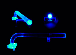
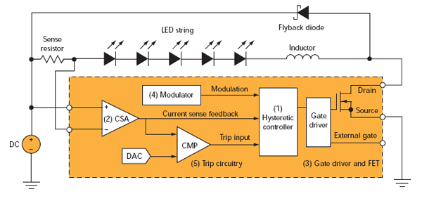
The main control system in any buck regulator is the hysteretic controller. This block regulates the current through the inductor by turning on a switch when it is below the lower threshold and vice versa. A shunt resistor is a convenient method of sensing the current, and by pairing it with a differential current sense amplifier (CSA), a smaller resistance can be used to minimize power losses. The analog circuitry of the controller uses the feedback from the CSA. These blocks can be arranged in various combinations. Different LED colors differentiate the topologies.

In all three topologies, current flows through the inductor when the corresponding switch (field-effect transistor, or FET) is turned on. When the current rises above a predetermined limit, the hysteretic controller on each topology turns off the FET. As the current in the inductor persists, it conducts through the flyback diode until it falls below the lower threshold and the FET is turned on again. A system capable of faster switching will require smaller inductors to store magnetic flux between alternate cycles.

The topology with the red LED is configured with a low-side sense resistor located on the source pin of an N-FET. An inherent problem with this implementation is that current through the inductor can only be sensed when the switch is on. Once the current reaches the peak threshold and the switch is turned off, the hysteretic controller must use a timing circuit to turn the switch back on.

If during the off cycle the falling current does not reach the lower threshold or overshoots it, the off-time must be adjusted until the loop is stable at the required current ripple. As this technique has true hysteresis on only one side of the loop, it won’t be able to quickly adjust to fast transients of source and load conditions.

A hysteretic control system that can sense both falling and rising edges requires the feedback loop to remain in the current path regardless of the state of the switch. The topology used by the blue LED shows the sense element in the path of the inductor current in the charging as well as discharging phase. To achieve this, a high-side switch or P-FET is used. Because the RDS (resistance offered by the FET to current) is higher in P-FETs than in N-FETs, there is a loss in efficiency. Additionally, the high-side driver and the P-FET itself are generally costlier than a low-side driver and N-FET rated for the same switching capability. Finally, in the topology used by the green LED, the FET and sense resistor swap positions. This permits the use of an N-FET to increase efficiencies while the location of the sensing element allows inductor current to be sensed throughout the operation of the hysteretic controller.

Working as a system, the LED driver channel depends on five elements to create a topology that is efficient and robust while meeting the demands of HBLED applications: the hysteretic controller, the current sense amplifier, the gate driver and FET, the modulator, and the trip circuitry. The same blocks may be used for other topologies such as boost, buck-boost, and single-ended primary inductor convertor (SEPIC). To Read (Part – II) Click Here.

Article is posted by Optics For Hire – Optical Design Consultants

What Is The Best Light Pipe For An Application?

flex_neon_reduced

There are two basic styles of LED light pipes – rigid and flexible.  A rigid light pipe is produced with a hard plastic material and will have either a vertical or a right-angle construction, capable of redirecting the LED’s light output to the desired location with minimal loss of intensity.  Rigid light pipes are ideal if the LED is mounted on a board immediately behind a front panel. Flexible light pipes are constructed with an optical grade plastic material that provides less rigidity allowing them to transport light from a board at custom, user-specified subtle angles ensuring easy integration around existing components.  Both rigid and flexible light pipes can come in single or multi-unit configurations. There are two basic formats of light pipes: vertical and right angle. Within both styles, the light pipe can either be a single unit or multiple unit and designed to a variety of shapes, including round or rectangular. A quality multi-unit light pipe will be designed to ensure there is no light bleed between adjacent light pipes. There are several construction options as well. Some to consider are: polycarbonate or optical grade materials; different shapes and lens caps; compatibility with either surface-mount or through-hole LEDs; and panel or PCB mounted.

A quality LED light pipe supplier will provide expert complimentary selection and integration support. They should ask questions like: Where is the light source coming from? How far back is the LED from the emitting source? What LED are you considering for the design? How much brightness is required? What amount of real estate is available to work with? Can the light be effectively routed in a right-angled application? What are the mounting considerations, i.e. friction or snap fit? What is in the path of the light transmission? Can the design provide uniform light performance? Generally speaking, the brightness emitted from a light pipe will be dependent upon the LED utilized, as well as the shape of the application.  A properly matched light pipe will emit approximately the same brightness as the individual LED, minimizing the amount of light lost.  An LED must be effectively matched to the entrance of a light pipe in order to allow for proper light capture with minimal light loss. Effective light pipe and LED matching occur only when the LED radiation pattern angle matches the acceptance pattern angle of the light pipe. The most effective light pipe and LED matching occurs when the LED is located inside the light pipe surface.  When the LED is embedded into the light pipe, 92% of the light rays emanate within the light pipe, allowing for minimal light loss.

Ray Tracing For LED Light Pipe Applications

Ray Tracing is a method for calculating the path of light through a light pipe.  State-of-the-art ray trace software with precise 3D CAD/CAM models can ensure proper design and optimal light transmittance, with minimal light is a three-step process. First, a three dimensional model, representing an original design concept of a light pipe is created using 3D CAD software to scale. This model is an accumulation of the physical dynamic of a specific light pipe application (including any bends, angles and material for light transmission). Secondly, an artificial LED is created, called an emitting disc, within the ray tracing program.  The emitting disc simulates the intensity and the viewing angle of an LED, which is placed on the surface of a light pipe model.  The detector plane is created in front of a surface where the light is intended to exit.  The combination of these two planes in the ray trace program determines the amount of light transfer from LED to the emitting surface of a light pipe.

lumexlightpipesilluminated

Finally, with a precise 3D model and proper LED viewing angle, it is then possible to run the design through cutting-edge ray tracing technology to test the exact light output in terms of both uniformity and brightness.  By measuring this light output via ray tracing, adjustments can be made to ensure that the most efficient light transmission path is identified and tested before any time or expenses are spent on tooling.

Ray tracing provides several key advantages for LED light pipe applications. First, precise product modeling ensures the most efficient possible design – providing maximum light transmissions and minimal light loss. Second, because ray tracing calculates optimal design for efficient performance before product tooling even takes place, time wasted on trial and error development is eliminated. This speeds time to market, enabling products to be developed up to 35% faster than is possible with traditional product design techniques. Also, the ability to ensure optimal design prior to product tooling, eliminates or reduces the expense on re-tooling and can generate up to 40% cost savings.

Standard Vs. Custom LED Light Pipes

LED light pipes, be they custom or standard technologies, are a cost-effective and highly efficient tool for transporting light to the user interface. Quality suppliers will have a wide array of standard light pipe technologies—single or array, molded or flexible, single or multi-color formats with right angle, vertical or horizontal packaging for either panel or PCB mounting. At the same time, exciting recent developments in ray tracing technology means that custom light pipes can be created for optimal performance in each unique application with great ease. Gone are the days when custom meant “expensive” and “slow.” Today custom light pipe technology optimizes performance and can generate significant cost savings and speed time to market.

Article is posted by Optics For Hire an Optics Component Manufacturing consultant.  

What You Need To Know About Illumination And Zemax Design

Illumination And Zemax Design

optical lens design,zemax zoom lens design,illumination design

Wide angle TIR LED lens

Illumination design is indeed a vital point of consideration whenever you get to talk about lens design. As a matter of fact, this particular division happens to be an important genre as well as a highly popular choice in shape of lens design. Illumination design happens to get so much of importance among the connoisseurs of the industry of lens design because it has the magical capacity of combining aesthetics as well as functionalities.

Zemax zoom lens design happens to form an integral part in the context of illumination design. With the help of zemax zoom lens design technologies optical lens design engineers can truly make it a point that they are going to offer a boost to the functionalities as well as range of a particular progressive lens. Let’s make it a point to throw light upon some of the most vital technicalities pertaining to high precision illumination design procedure.

Laser systems

Laser systems appear to be an important part and parcel that has a close connection with illumination design as well as zemax zoom lens design technologies. As a matter of fact, with the help of laser technologies optical lens design engineers can make it sure that the functionalities relating to various types or categories of lenses reach the culminating point of perfection. This is the reason why these systems happen to be really important in lens designing and development industry.

Diffractive optical lens design

zemax zoom lens design,optical lens design

LED projector with TIR lens

Diffractive optical lens design is an important part of lens designing and development industry. Whenever it comes to the issue of taking great care of the sub wave length issues (binary) that pertain to different varieties of lenses it is diffractive optical lens design technology that comes into forefront. As a matter of fact, this particular genre of lenses happens to be quite popular with a number of people who really care about quality lenses. According to many people in the lens design industry Diffractive optical lens design happens to be a much better choice compared to conventional lenses.

Grating analysis

Grating analysis happens to be a highly important issue that has a close connection with the process of lens design. If you have to make it sure that all the designing technologies as well as principles are going to be implemented in the right fashion and if you have to make it sure that you are going to get the right kind of functionalities out of the lenses that you are going to use than efficient handling of grating analysis is a must. This particular technology is really going to come handy to design professionals as well as design engineers in terms of getting the right kind o result out of wave analysis. Therefore, you can pretty well figure it out that significance of this particular technology is not to be gainsaid in any way.

All the aforementioned aspects happen to be immensely crucial in connection with illumination design as well as zemax zoom lens design.